Micro Lens
The example is an adaption to the single photon source design in Gschrey et al. [1]. The geometry consists of a multi-layer substrate which serves as Bragg mirror and a micro lens on top, a quantum dot is situated within the top layer:

Schematics of the geometry of a micro lens with Bragg mirror (rotationally symmetric)
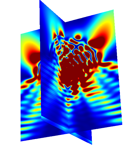
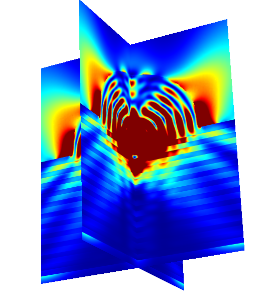
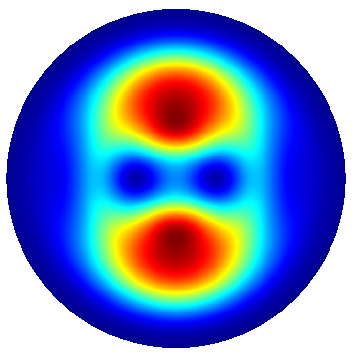
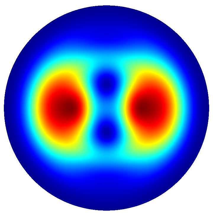
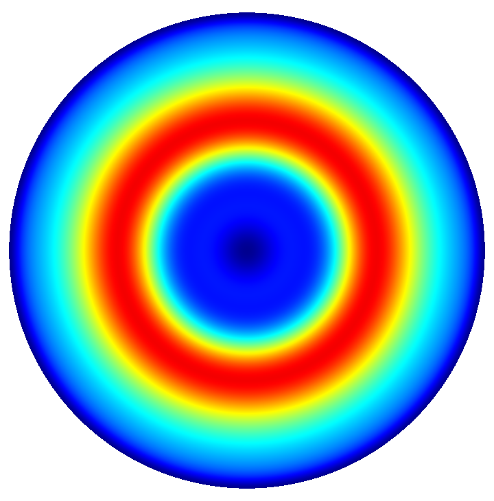
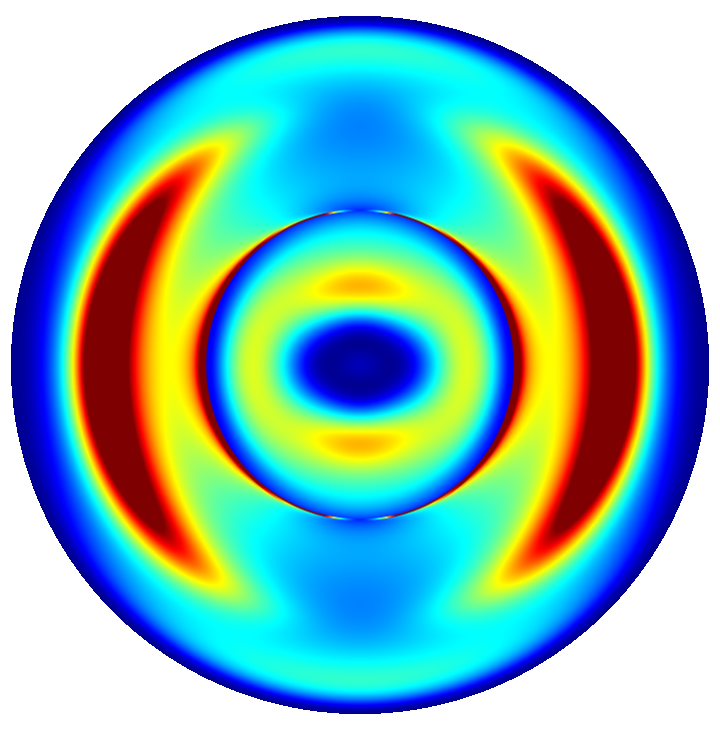
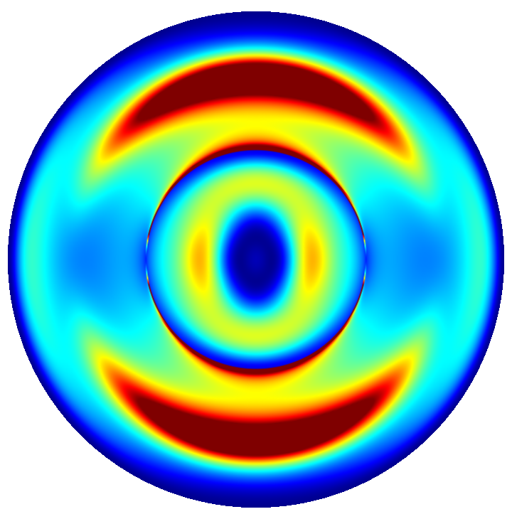
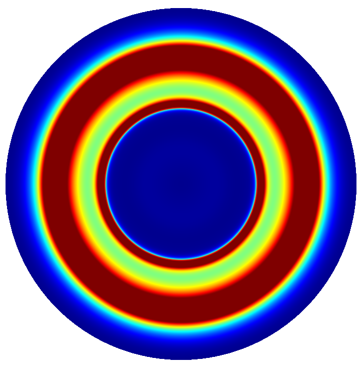
Near field and far field plots @ 
The following figures show near field intensities and far fields of three dipoles with different polarizations for a spherical micro lens (with different scalings of the pseudo color plots):
|
|
|
 ,
,  , and
, and  -polarized dipoles (@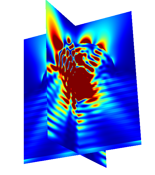
|
|
|
|
|
|
Bibliography