Rotationally Symmetric Emitter
The example is taken from Gregersen et al. [1]. The geometry is a non-ideal micro pillar:
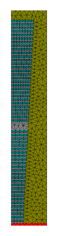
Single Photon Pillar Emitter (rotationally symmetric)
The multilayers are simply created in the layout file layout.jcm by the special primitive MultiLayer whose outer shape is a trapezoid (see below ).
Parameter scan
The Matlab® script data_analysis/run_scan_wavelength.m provides a scan over the wavelength of the dipole source producing the following plots showing the efficiency and the Purcell factor of the device (here for a straight pillar):
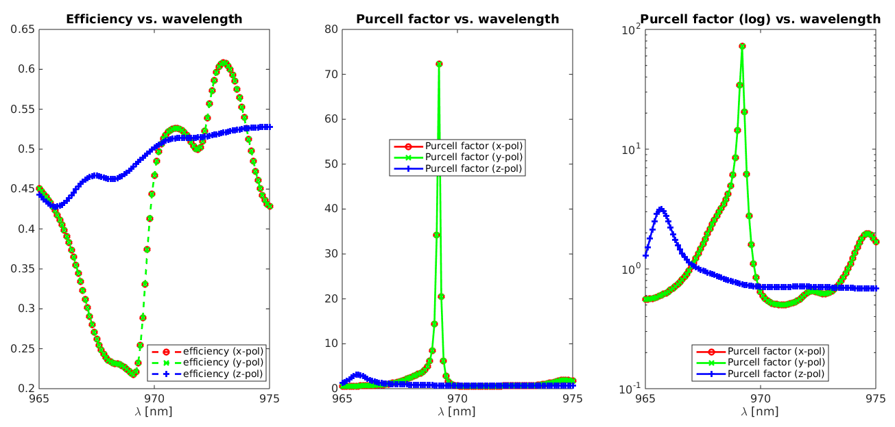
Left: Efficiency of the micro-pillar emitter with respect to the wavelength. Right: Purcell factor
Warning
As the sampling rate of the wavelength scan was  the maximum value of the Purcell factor is missed (much higher than 80).
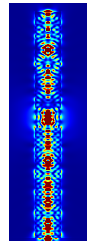
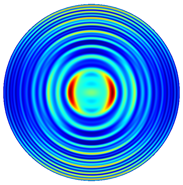
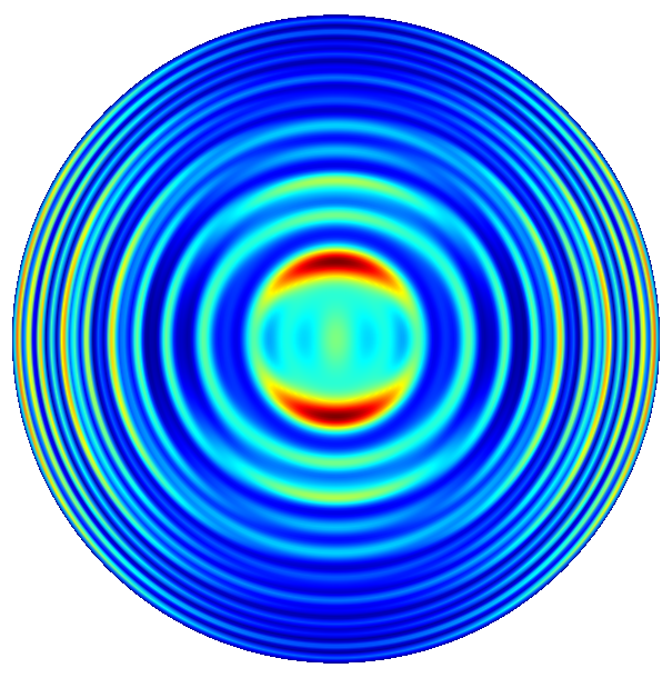
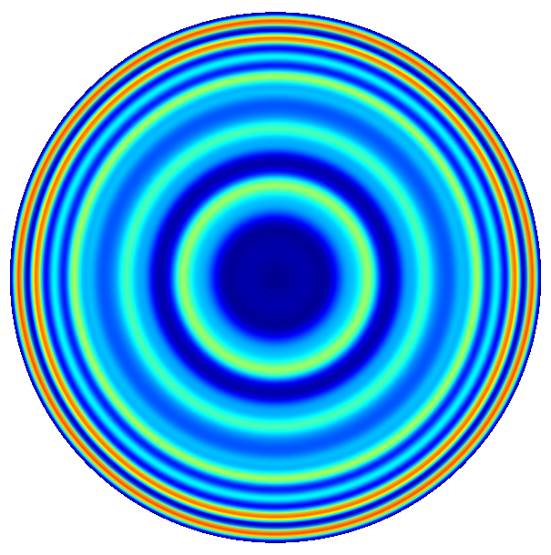
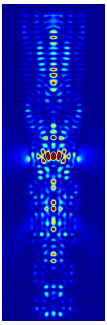
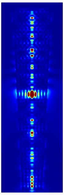
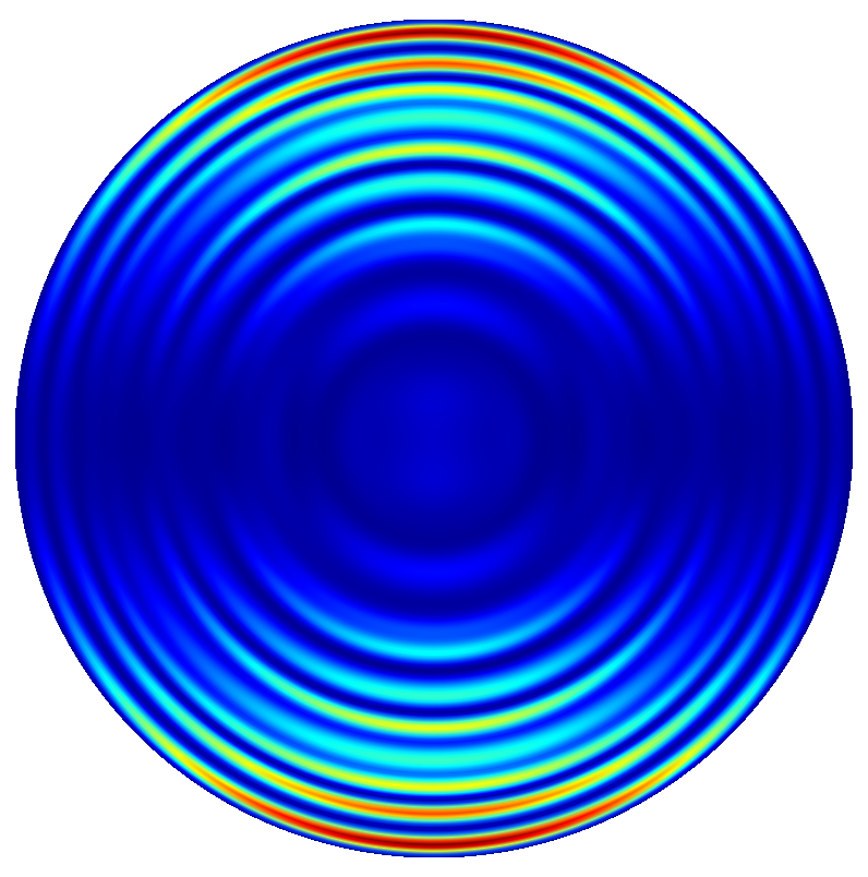
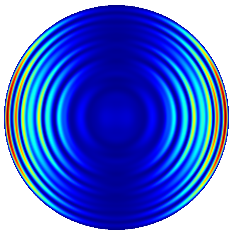
Near field and far field plots @ 
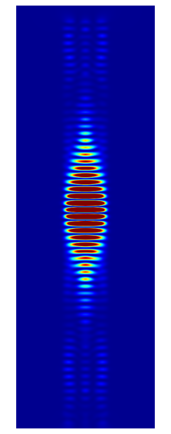
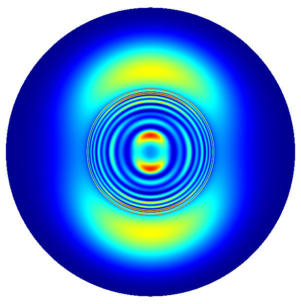
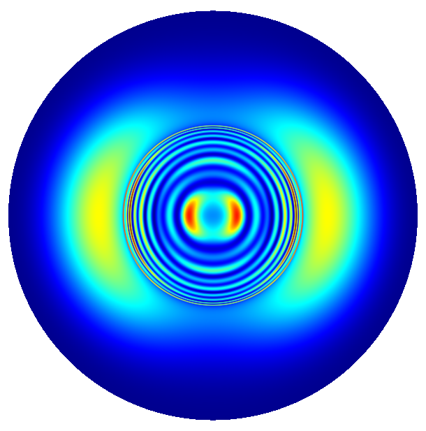
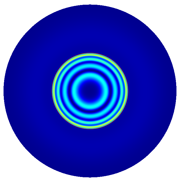
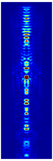
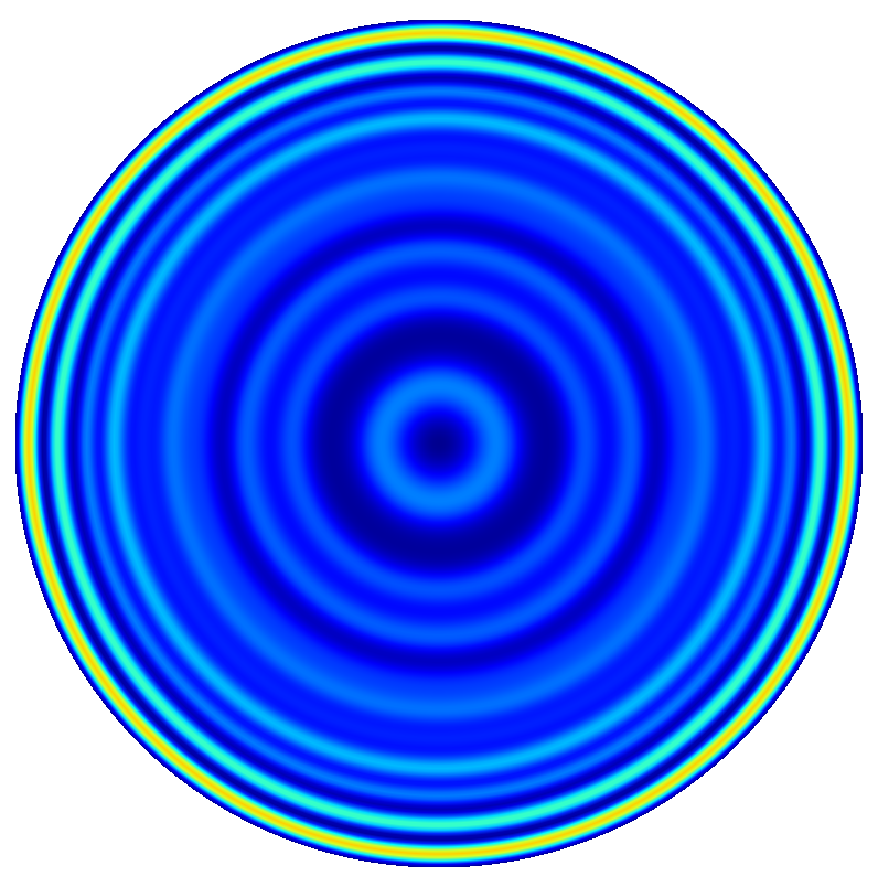
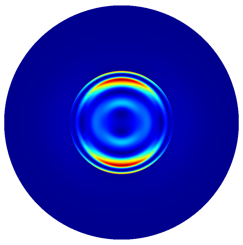
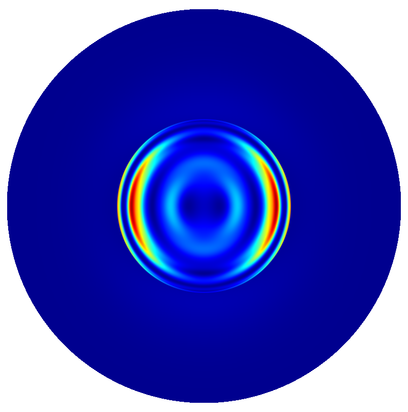
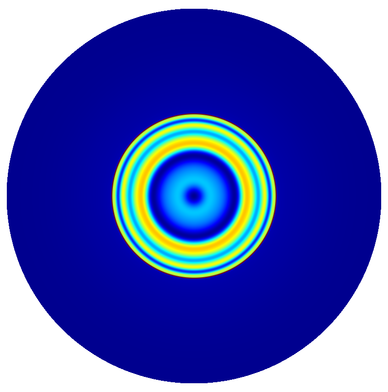
The following figures show the near field intensities and the far fields of the three dipoles for a straight pillar and the above non-perfect pillar
Straight Pillar
(The false color plots for the vertical dipole  -polarized is differently scaled to the horizontal dipoles).
|
|
|
 ,
,  , and
, and 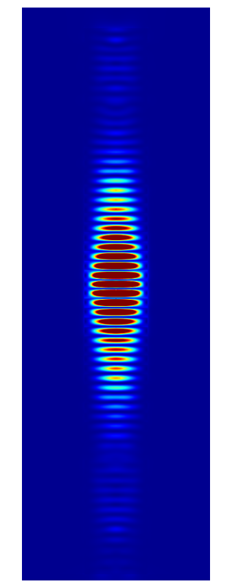
|
|
|
|
|
|
Trumpet Pillar
|
|
|
|
|
|
|
|
|
Definition of the multilayer stack
To define the multilayer stack we used
MultiLayer {
   ...
  SubLayers {
    Layer {
      DomainId = 2
      Height = 79
    }
    Layer {
      DomainId = 3
      Height = 72
    }
    Multiplicity = 29
  }
  Layer {
    DomainId = 2
    Height = 79
  }

  Layer {
    DomainId = 3
    Height = 294
  }

  SubLayers {
    Layer {
      DomainId = 2
      Height = 79
    }
    Layer {
      DomainId = 3
      Height = 72
    }
    Multiplicity = 26
  }

   ...
}
The sections Layer and SubLayers are used to define the repeated layers. The excitation are dipole sources placed in the center layer of the pillar. In a post-process we compute the dipole emission and the Fourier transform of the far field.
Bibliography