Micro Pillar
The example is inspired by Gregersen et al. [1] where a quantum dot is placed in a micro pillar to produce a single photon source. However, we have simplified the problem so that the 3D computations run smoothly on a laptop computer:
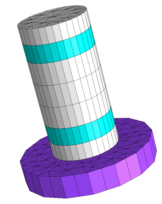
Micro cavity geometry
Note
Exploiting the rotational symmetry of the geometry, the same problem is solved in the next section Rotationally Symmetric Emitter.
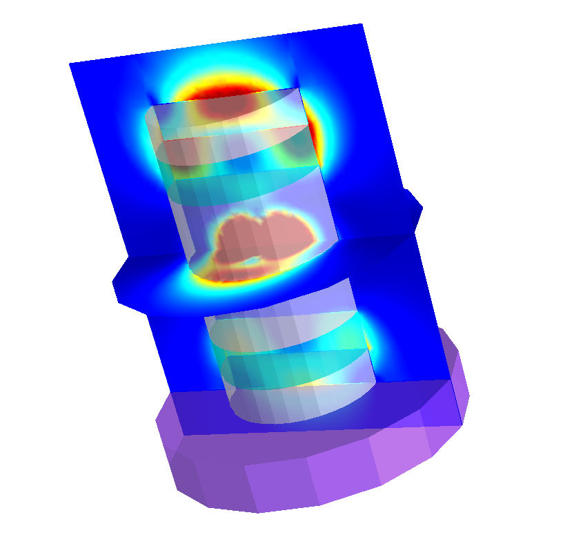
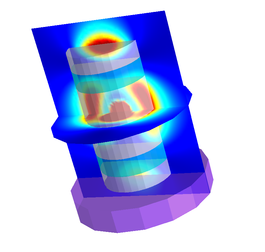
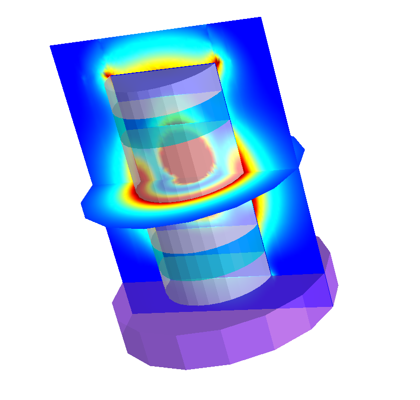
The following figure shows the field intensities for  ,
,  , and
, and  -polarized dipoles placed in the center of the cavity.
|
|
|
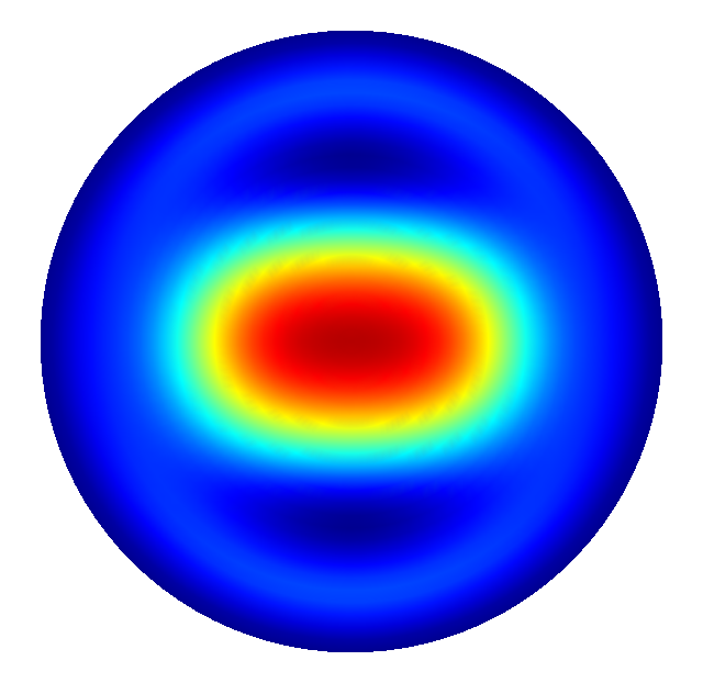
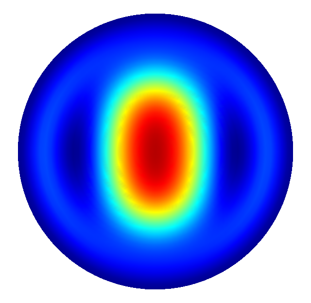
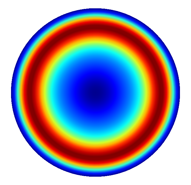
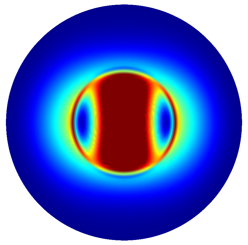
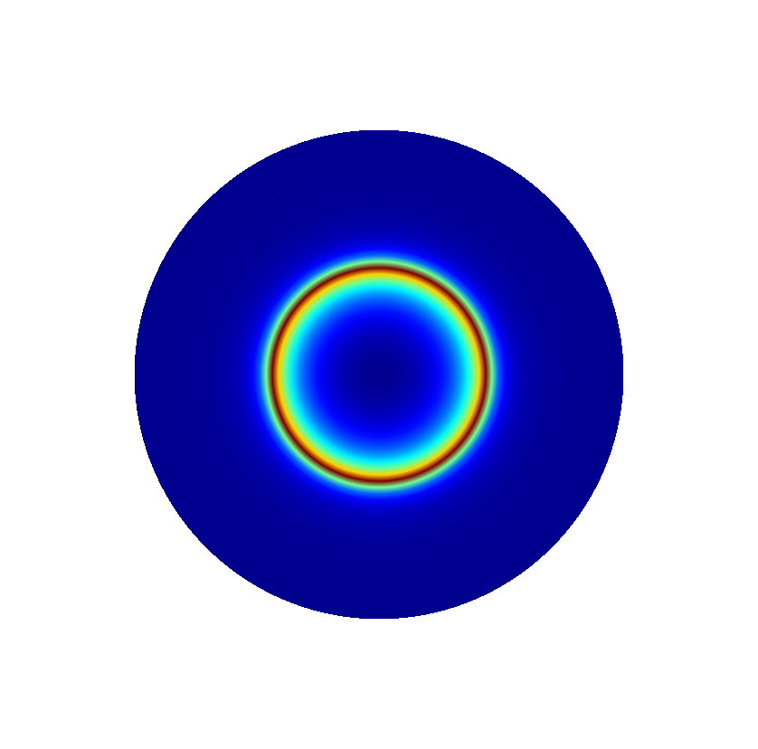
The far field data is the electromagnetic field on a infinitely far distant hemisphere above or below the micro pillar. As normalization, the far field data as returned by the FarField post process, refers to a hemisphere with distance  to the origin. The outputs of the
 FarField yields these fields in 2D polar coordinates. JCMsuite visualizes the far field on a polar disk:
|
|
|
|
|
|
Parameter Scan