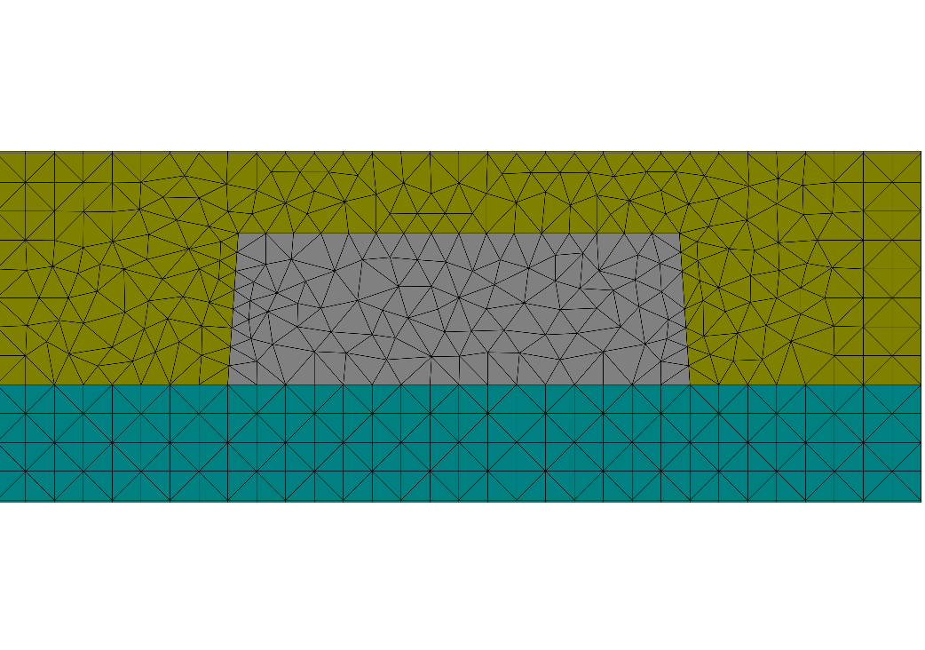
Line Grating
This is a simple example for a 1D periodic line grating. The periodic unit cell contains the 2D cross-section through the grating. In this case the cross-section of the line has a trapezoidal shape, it is situated on a substrate and surrounded by a background material. The materials in the example are chosen as chrome (line), glass (substrate) and air (background).
The grating is illuminated by plane waves with  and
and  polarization.
JCMsuite computes the near field distributions.
The following figures show the near-field intensities within the structure for
perpendicular plane wave incidence from the substrate side at a wavelength of  .
.
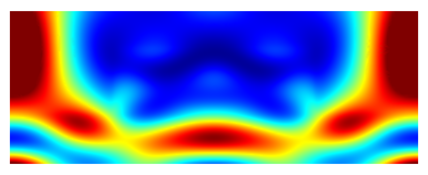
Near field intensity for -polarized illumination
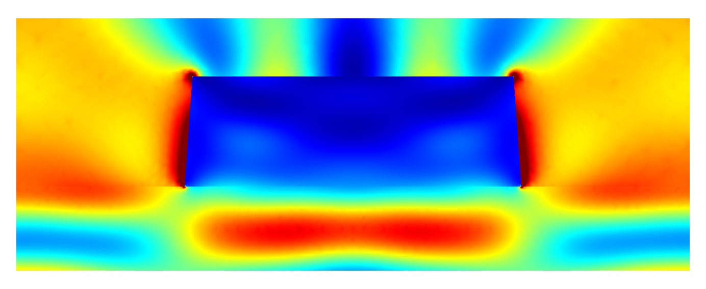
Near field intensity for -polarized illumination
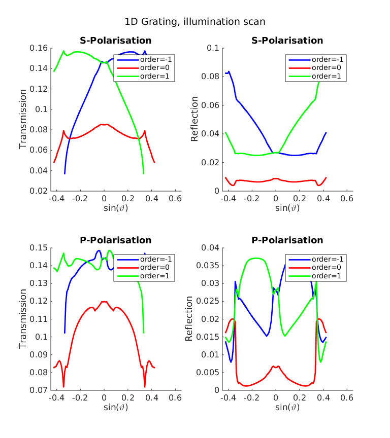
The post process FourierTransform computes the amplitudes of the transmitted diffraction orders.
Parameter scan
The Matlab® script data_analysis/run_scan_illumination.m provides a scan over the incidence angle.
It produces the following plots showing the intensities for reflected and transmitted diffraction orders:
In the script data_analysis/run_scan_width.m the width of the line varies from  to
to  with fixed illumination angle.
This yields the following line width dependencies:
with fixed illumination angle.
This yields the following line width dependencies:
