Exploiting Mirror Symmetry
With this project you solve precisely the same project as in the parent section but only on the right half computational domain equipped with mirror boundary conditions. Since the incoming fields are not mirror symmetric, the fields are expanded into two discrete modes (symmetric- and anti-symmetric fields). This is done automatically by the solver.
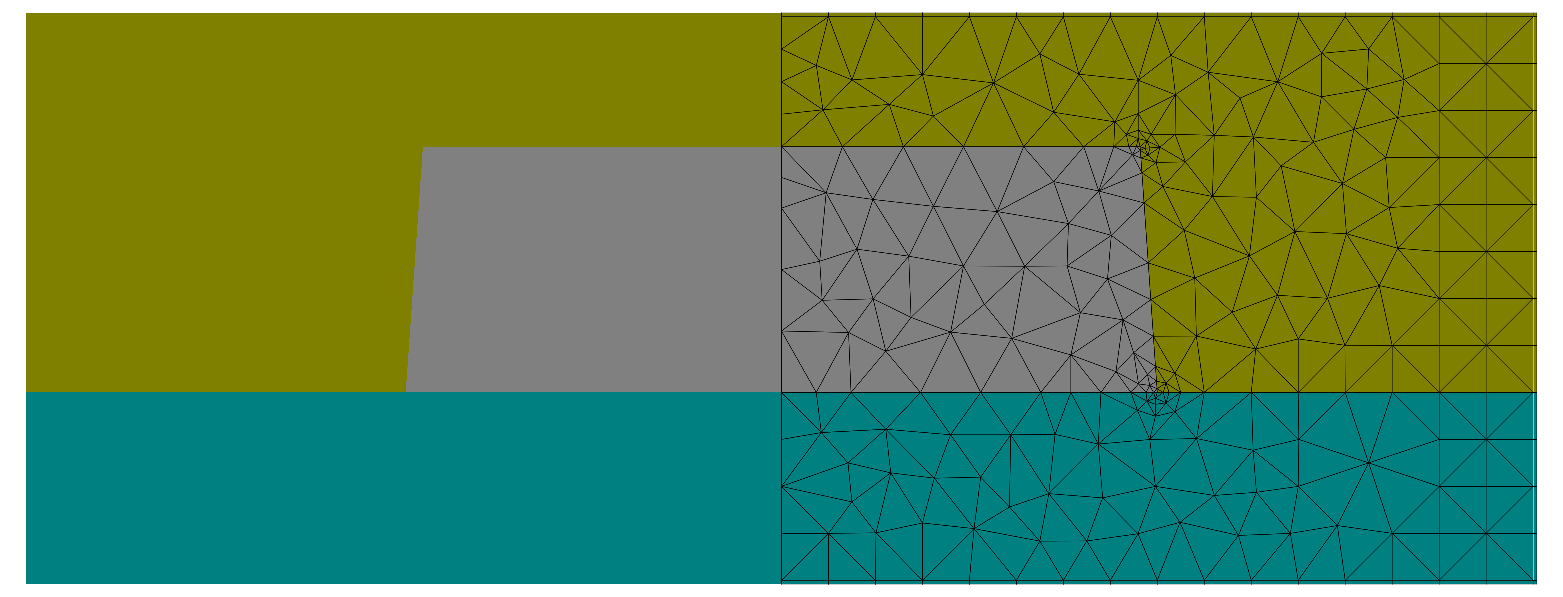
Mesh with mirror symmetry applied. The geometry is discretized only on a half domain.
Note
Compared to the full problem simulation, a significant reduction of the computation time is not expected for 2D problems. (For 3D problem using mirror symmetry is highly recommended).
To impose mirror boundary conditions the computational domain is restricted to the right half of the structure and BoundaryClass is changed to Mirror for the West segment:
Layout2D {
  ...
  Objects{
    Parallelogram {
      DomainId = 1
      Priority = ComputationalDomain
      ...
      Boundary {
        Class = Transparent
      }
      Boundary {
        Number = West
        Class  = Mirror
      }
    }
    ...
  }
}
Another way to define mirror symmetric boundary conditions is described in the mirror symmetric Slit example. There, a global definition of the BoundaryConditions is used.